This post describes my first steps with ESP32. It was originally written as preparation for TA’ing communications week in MIT’s fabclass. I cover basic setup, firmware deployment and a hint of benchmarking.
Warning: This post was written in November 2016. ESP32 is brand spanking new and should be considered a moving target.
Contents:
What is the ESP32?
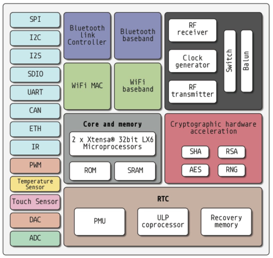
ESP32, successor to the beloved ESP8266, is system on a chip (SoC) that can do (almost) anything:
- Real concurrency with two cores
- WIFI
- Bluetooth
- BLE
- Much more
Espressif, the manufacturer, have been kind enough to send some units of their new ESP32 modules for evaluation. (huge thanks to John Lee @EspressifSystem) I will demonstrate basic connectivity, different ways to program it, and basic benchmarking.
Hardware Setup
Equipment Used
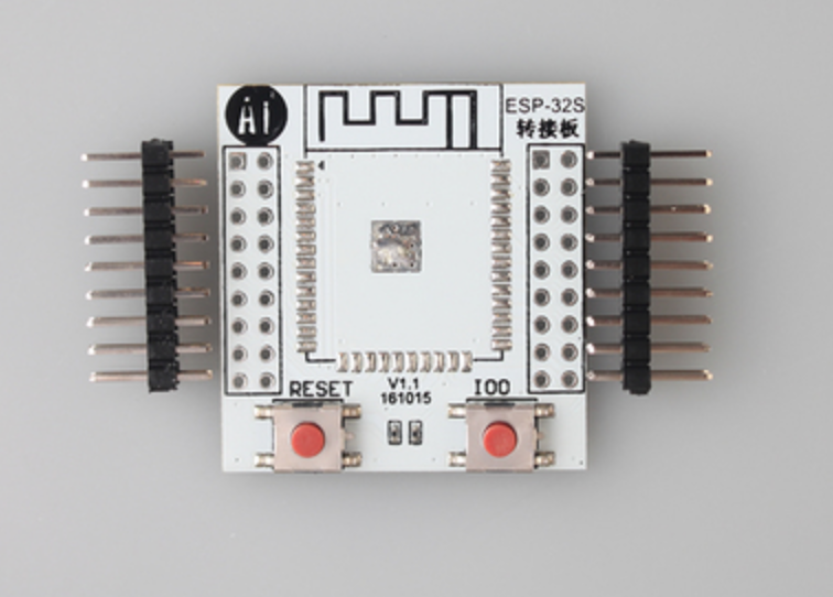
- ESP32 WROOM32 module. This is Espressif’s own ESP32 module. It’s safe to assume that we’ll see ESP32 used in modules from 3rd party manufacturers in the near future (AI was the lead module manufacturer for the ESP8266).
- ESP32 Breakout board. Espressif provided us with simple breakout boards that expose all I/O pins and physical buttons for RESET and BOOT MODE. There are other boards available to order as well as designs to mill your own.
- FTDI Cable
- 3.3V Power Supply (up to 500mA). DO NOT USE THE FTDI POWER - IT CAN’T PROVIDE ENOUGH CURRENT. (TRUST ME - I’VE TRIED)
Note: soldering the module to the breakout board proved non-trivial, the ground plane is very large so a high wattage soldering iron is recommended for soldering the ground pads.
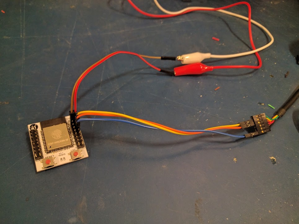
Basic Connectivity
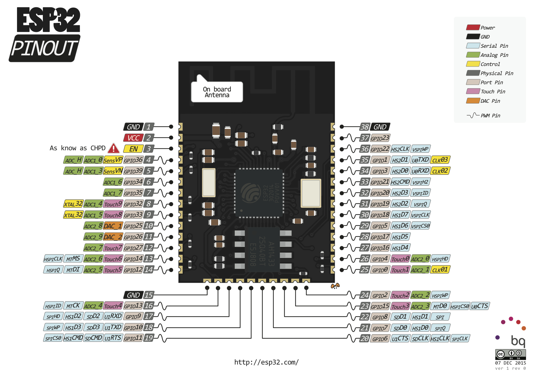
- VCC (ESP32) -> 3.3V (POWER)
- GND (ESP32) -> GND (POWER)
- GND (ESP32) -> GND (FTDI)
- TX (ESP32) -> RX (FTDI)
- RX (ESP32) -> TX (FTDI)
Sanity Check
- Open a terminal emulator on the FTDI port with a BAUD rate of 115200
- Hit the RESET button
⇒  miniterm.py /dev/tty.usbserial-XXXXXXXX 115200
ets Jun  8 2016 00:22:57
rst:0x1 (POWERON_RESET),boot:0x13 (SPI_FAST_FLASH_BOOT)
....
IDF version : master(db93bceb)
WIFI LIB version : master(934d079b)
ssc version : master(r283 4d376412)
!!!ready!!!
mode : softAP(26:0a:c4:00:27:f4)
dhcp server start:(ip: 192.168.4.1, mask: 255.255.255.0, gw: 192.168.4.1)
+WIFI:AP_START
Not only does it work, it even defaults to opening a public access point
⇒  airport -s | grep ESP
ESP_0027F4 26:0a:c4:00:27:f4 -14  1,+1    Y  -- NONE
When a device enters the network:
n:1 0, o:1 0, ap:1 1, sta:255 255, prof:1
add 1
station: 80:e6:50:27:b6:62 join, AID = 1, g, 20
+SOFTAP:STACONNECTED,80:e6:50:27:b6:62
I couldn’t find any other interesting things in the provided firmware. In case you were wondering, like me, whether ESP8266’s AT command-set works in this prompt, the answer is no. It’s not very clear what commands do work here. (If you know of some, leave them in the comments below)
Programming
FreeRTOS
Before programming this chip it’s crucial to understand that, unlike other embedded systems, the ESP32 comes with a light operating system - FreeRTOS. The following methods to program this chip don’t replace the FreeRTOS firmware, but rather deploy applications for it to run. I imagine that in the near future we’ll see other operating systems or no-os approaches for reprogramming these chips.
There are currently two methods to program the ESP32: the ESP-IDF and the ESP32 arduino Core.
ESP - IDF
Espressif IoT Development Framework is a set of open source libraries and tools to facilitate deployment of apps to ESP32s FreeRTOS.
Code Example : HTTP GET request using the ESP IDF
ESP32 ARDUINO CORE
Espressif have also been hard at work to get the maker community happy and makers love Arduino. The ESP32 arduino core integrates ESP-IDF deeply into the arduino tools. This includes providing a WiFi API that is almost 100% compatible with existing wifi shields for arduino.
Code Example : HTTP GET request using the ESP32 Arduino Core
Note: currently, to take advantage of the concurrency capabilities - IDF is the way to go.
Ring Oscillator benchmark
Ring oscillator tests measure the minimal amount of time it takes for a signal to get out of a chip and back through peripherals.
In practice, it means shorting two pins with a jumper, defining one as input and the other as output, and then writing and reading as fast as possible. The result is recorded with an oscilloscope connected to the shortened pins and ground.
Here, I measure both programming methods mentioned earlier:
| FreeRTOS (code) | Arduino Core (code) |
|---|---|
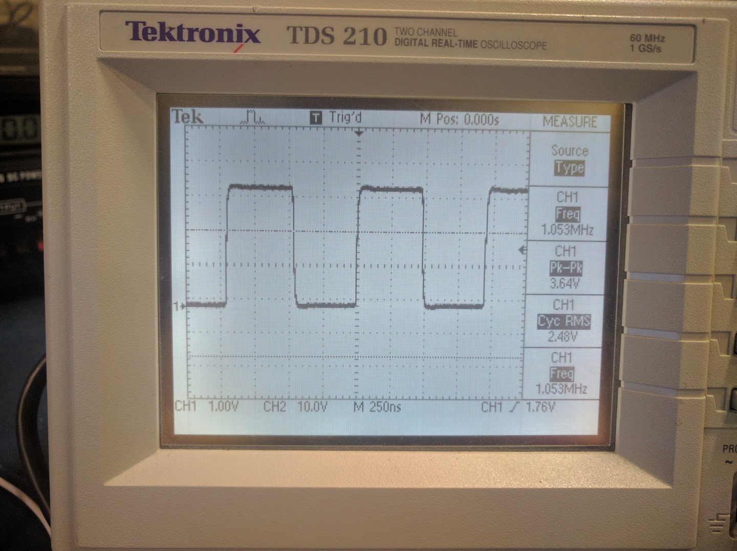 1.63MHz 1.63MHz |
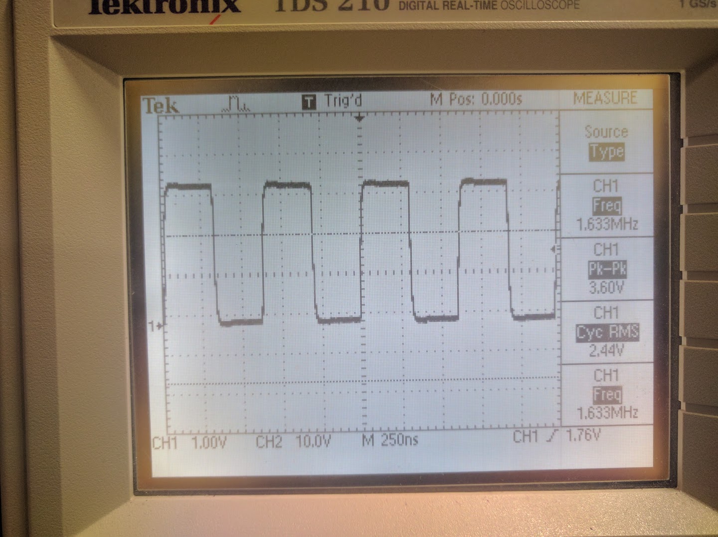 1.05MHz 1.05MHz |
Conclusion: the Arduino program is about 35% slower than the lower level FreeRTOS program. However, usually in these type of tests, the portability of arduino code comes with a much bigger performance drop. Good job, Espressif!
Note: These tests only occupy one core. The second core is free to perform other tasks, such as networking. Example.
More Resources
Thanks:
- John Lee and espressif for providing the hardware.
- Tal Achituv for help with soldering and the oscilloscope.
- Jonathan Bobrow for feedback on this post.